
T: +86-18906892820
F4-19037-6#, Yiwu Intl Trade Mart, Yiwu Jinhua, Zhejiang, China (Mainland)

Views: 141 Author: Site Editor Publish Time: 2026-09-12 Origin: Site


Interrupting high-voltage distribution circuits carries severe risks. Attempting to break load without verifying equipment thresholds frequently results in severe arc flashes, equipment destruction, and fatal injuries. Utility safety managers and linemen face operational ambiguity when matching portable loadbreak tools to varying grid voltages. Transitioning between 15kV, 25kV, and 34.5kV systems often leads to improper tool deployment and regulatory compliance violations. To mitigate these risks and ensure safe switching operations, procurement teams and field operators must strictly evaluate specific voltage, amperage, and transient recovery ratings before selecting or deploying a load bust tool.
System Voltage Alignment: The tool’s maximum design voltage must always meet or exceed the system’s maximum phase-to-phase operating voltage, regardless of grounding configurations.
Amperage Ceilings: Standard load bust tools are designed for specific nominal and maximum continuous loads (typically 600A nominal / 900A maximum); they are strictly for load switching, not fault clearing.
Equipment Limitations: Standard cutouts and disconnects are not rated to drop significant load (e.g., 100 amps) independently; a rated loadbreak tool is a non-negotiable requirement for these operations.
Dual-Rating Awareness: Many industry-standard tools feature dual ratings (e.g., 25/34.5 kV), requiring operators to understand the difference between grounded and ungrounded system applications before use.
Procurement Strategy: Standardizing on a tool rated for the highest voltage class in your distribution network (e.g., 34.5kV) prevents cross-deployment errors and improves overall safety scalability.
Opening a live distribution circuit under load is dangerous. Field operators routinely open disconnect switches, solid blade cutouts, and power fuses. You do this to isolate line sections, perform maintenance, or reroute power without dropping an entire feeder. Doing this safely requires specialized equipment designed specifically to manage the plasma arc generated during contact separation. Relying on the physical separation of standard switchgear components guarantees equipment failure.
Standard cutouts and disconnect switches lack the internal mechanisms required to extinguish an electrical arc. When you pull a standard cutout under even a moderate load of 100 amps, the surrounding air instantly ionizes. This ionization creates a highly conductive plasma channel that allows current to continue flowing across the expanding physical gap. Because standard cutouts operate in open air, they cannot stretch, cool, or de-ionize this plasma rapidly enough to break the circuit. The resulting sustained arc travels upward. It can bridge adjacent phases, destroy the switchgear, and expose the operator to extreme thermal radiation and molten metal.
Portable loadbreak tools solve this physical limitation by providing a controlled, enclosed environment for arc interruption. When an operator attaches the tool across a cutout and pulls the hot stick, they are not directly pulling the switch open. The downward motion charges a heavy-duty internal spring mechanism. Once a specific mechanical tension threshold is reached, the tool's internal contacts snap open at exceptionally high velocity. This rapid separation draws the arc inside a specialized trailer tube lined with ablative material, typically polyacetal or Delrin.
The extreme thermal energy of the arc instantly vaporizes the inner surface of this ablative material. This vaporization outgasses a massive volume of high-pressure, un-ionized gas directly into the arc path. The sudden blast of gas cools the plasma, stretches the arc, and rapidly restores the dielectric strength of the gap. When the alternating current naturally crosses the zero-point in its sine wave, the arc is permanently extinguished. The circuit breaks safely within milliseconds.
Verifying the maximum operating voltage of a portable loadbreak tool is the most important pre-operation check a lineman performs. The nameplate voltage rating represents the absolute physical limit of the tool's ability to prevent an arc from restriking after the initial interruption. Distribution grids frequently operate at voltages slightly higher than their nominal classifications. A nominal 14.4kV system might experience localized swells or operate closer to 15kV depending on substation regulation. Operators must ensure the tool's maximum design voltage strictly exceeds the grid's highest possible operating voltage.
Many industry-standard tools feature dual-voltage nameplates, such as 25/34.5 kV. This frequently causes confusion in the field. These dual ratings tie directly to the grounding configuration of the specific distribution system.
The lower rating dictates the maximum safe operating threshold for ungrounded systems, impedance-grounded systems, or single-phase-to-ground applications. In ungrounded configurations, the recovery voltage across the open switch contacts can equal the full phase-to-phase potential of the system. If you operate on a 25kV ungrounded system, the tool must be rated for at least 25kV to handle the full line-to-line recovery voltage.
The higher rating applies strictly to solidly grounded systems. On a solidly grounded grid, the voltage stress across the open contacts during a single-phase switching operation is limited to the phase-to-ground voltage. This is significantly lower than the phase-to-phase voltage. A tool rated for 34.5kV on a grounded system relies on the fact that it will only ever see the phase-to-ground potential during a normal switching operation.
Technical evaluations must always default to phase-to-phase voltage parameters rather than phase-to-ground measurements. Evaluating based on phase-to-phase voltage accounts for worst-case switching scenarios. If an operator assumes a phase-to-ground voltage limit but encounters an unexpected ungrounded fault condition down the line, the tool faces the full line-to-line potential. If the tool is only rated for the phase-to-ground voltage, the internal gap will fail to hold back the system pressure. This results in an immediate and violent restrike.
Beyond the steady-state voltage, operators must account for Transient Recovery Voltage (TRV). TRV refers to the high-frequency voltage spikes that bounce back across the open contacts in the microseconds immediately following arc extinction. When the arc goes out at the current zero-crossing, the system voltage attempts to re-establish itself across the gap. If the tool's internal dielectric recovery is slower than the rising TRV, the arc will punch through the gas and re-ignite. High-quality tools feature specific stroke lengths and exhaust venting to withstand severe TRV profiles. Exceeding the nameplate voltage guarantees the TRV will overwhelm the tool's dielectric capabilities.
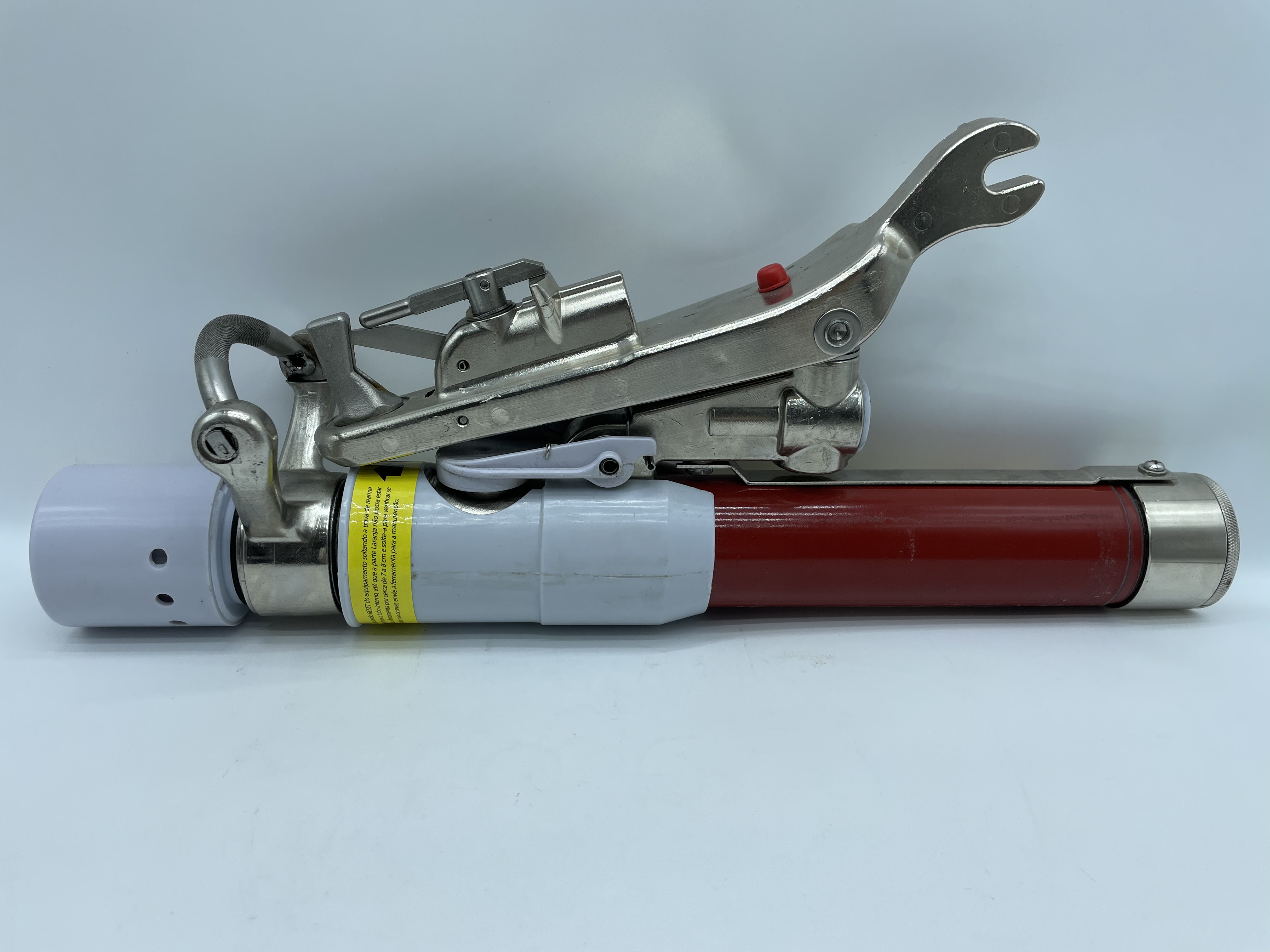
Voltage dictates the tool's ability to prevent a restrike. Amperage dictates the physical wear and thermal stress the tool endures during the interruption process. Standard industry tools typically display two distinct amperage metrics: a continuous nominal rating and an absolute maximum interrupting rating. Understanding the operational difference between these two numbers prevents premature equipment degradation.
A nominal rating of 600 amperes indicates the tool can repeatedly interrupt loads up to this threshold without requiring immediate maintenance or suffering severe degradation of its internal ablative materials. The maximum rating, typically 900 amperes, represents an emergency switching ceiling. Operating a tool at its maximum amperage rating generates significantly more thermal energy. It vaporizes a larger layer of the trailer tube and causes heavier pitting on the internal copper and tungsten contacts. Repeated operations at the maximum rating rapidly exhaust the tool's lifecycle and demand immediate teardown and inspection.
The most important safety distinction field personnel must understand is the difference between load switching and fault clearing. Portable loadbreak tools are engineered exclusively for load currents and parallel currents. They possess absolutely zero fault-interrupting capacity. Fault currents on distribution lines can easily exceed 10,000 amperes. If an operator mistakenly uses a load bust tool to open a switch on a faulted circuit, the extreme energy of the fault arc will vaporize the internal ablative material faster than the exhaust vents can clear the gas. This creates instantaneous, massive internal overpressure that exceeds the burst strength of the fiberglass housing. The tool will explode violently in the operator's hands.
Switching capacitive loads, such as capacitor banks or long runs of underground shielded cable, introduces severe complications that require specialized evaluation. In a capacitive circuit, the alternating current leads the voltage by 90 degrees. When the tool extinguishes the arc at the current zero-crossing, the system voltage is simultaneously at its absolute peak. This traps a massive peak-voltage charge on the disconnected capacitor bank.
Half a cycle later, the source voltage reverses polarity. The voltage across the open contacts of the tool is now the sum of the source voltage and the trapped capacitor voltage. This effectively doubles the recovery voltage stress. This severe TRV phenomenon tests the absolute dielectric limits of the tool. Manufacturers apply strict derating factors for capacitive switching. A tool rated for 600 amps of resistive load might only be rated to drop 250 amps of capacitive load. Attempting to drop a large capacitor bank without verifying these specific capacitive ratings frequently results in explosive restrikes.
Procurement teams and safety managers bear the responsibility of aligning tool specifications with the physical realities of the grid infrastructure. Selecting the right equipment requires balancing grid compatibility, physical ergonomics, and long-term maintenance requirements.
Auditing the current infrastructure is the first step in establishing grid compatibility. Many utilities operate legacy grids with a mix of 14.4kV, 25kV, and 34.5kV distribution lines. Purchasing voltage-specific tools for each distinct area creates a severe logistical hazard. If a 15kV-rated tool is accidentally transferred to a truck servicing a 34.5kV zone, the risk of a fatal deployment error increases exponentially. To prevent field mix-ups, safety managers often standardize on a single, high-capacity model rated for the highest voltage class in their network. Deploying 34.5kV tools universally ensures that no matter where a lineman operates, the tool exceeds the system parameters.
Standardizing on the highest voltage rating introduces physical trade-offs regarding weight and ergonomics. The physics of arc interruption dictate that higher voltages require longer internal stroke lengths to stretch the arc and sufficient ablative material to cool it. A 34.5kV tool is inherently longer and heavier than a 15kV tool. Operating a heavy tool at the end of a 35-foot telescoping hot stick requires significant upper body strength and balance. Lineman fatigue directly impacts safety. A heavy tool swaying in high winds is difficult to seat properly on a cutout, increasing the risk of a slip during the high-tension pull.
Mechanical compatibility with existing switching devices is equally important. Verifying the voltage and amperage ratings is entirely moot if the tool does not mechanically seat correctly on the switchgear. Operators must ensure the tool's upper anchor securely engages the attachment hook on the cutout, and the lower pull-ring hook fits smoothly through the fuse tube ring. Different manufacturers produce varying geometries for cutouts, solid blade disconnects, and power fuses. If the tool's anchor slips off the cutout hook during the downward stroke, the internal mechanism will not trip. The physical fuse tube will be pulled open, drawing an uncontrolled, uncontained arc in the open air.
Lifecycle tracking and maintenance cycles must also factor into procurement decisions. Every successful interruption consumes a microscopic layer of the internal trailer tube and creates carbon deposits. Premium tools feature built-in mechanical operation counters that increment with every trip. These counters eliminate guesswork, allowing safety managers to dictate precise maintenance schedules based on actual usage rather than calendar days. Once the counter reaches the manufacturer's specified limit, the tool must be removed from service for a complete teardown, cleaning, and replacement of the arc-quenching components.
Distribution System Voltage and Equipment Rating Compatibility
System Configuration | Maximum Operating Voltage | Required Tool Rating (Minimum) | Grounding Consideration |
|---|---|---|---|
14.4 kV Nominal | 15.0 kV | 15 kV | Suitable for solidly grounded or ungrounded systems. |
25 kV Nominal (Solidly Grounded) | 27.0 kV | 25/34.5 kV Dual Rated | Phase-to-ground voltage remains within safe limits for dual-rated tools. |
25 kV Nominal (Ungrounded) | 27.0 kV | 27 kV or 34.5 kV Single Rated | Must evaluate based on full phase-to-phase recovery voltage. |
34.5 kV Nominal (Solidly Grounded) | 38.0 kV | 34.5 kV | Strictly limited to solidly grounded applications to manage TRV. |
Even the most accurately specified tool becomes a severe hazard if field implementation protocols and maintenance standards degrade. The operational environment of overhead distribution exposes equipment to harsh elements, physical impacts, and constant UV radiation. All of these compromise the tool's safety ratings over time.
Identifying nameplate degradation is a mandatory field protocol. The manufacturer's nameplate contains the definitive voltage, amperage, and capacitive switching limits. Prolonged exposure to sunlight and harsh weather causes these labels to fade, peel, or become illegible. If a lineman cannot definitively verify the voltage rating by reading the nameplate in the field, the tool must be immediately removed from service. Relying on memory or assuming the rating based on the tool's physical size is a direct violation of safe switching practices.
Dielectric integrity relies entirely on the condition of the external fiberglass housing. The nameplate voltage rating assumes the fiberglass tube is pristine. Field personnel must physically inspect the tool body for deep abrasions, gouges, or exposed fiberglass fibers. Exposed fibers absorb atmospheric moisture, severely degrading the tool's insulating properties. Operators must check for carbon tracking. These are faint black lines on the fiberglass caused by previous minor surface arcs. Moisture or carbon tracking creates a conductive path along the outside of the tool. If a flashover occurs along the exterior surface, it bypasses the internal arc-quenching mechanism entirely, exposing the operator to the full energy of the arc.
Executing a strict pre-operation inspection checklist mitigates mechanical failures during deployment. Before attaching the tool to a hot stick, the lineman must follow these steps:
Verify the internal mechanism is fully reset. Attempting to operate a cutout with a partially tripped tool guarantees a sustained open-air arc.
Test the stroke mechanism for binding. If the internal tube does not slide smoothly, carbon buildup or internal damage has occurred.
Visually inspect the exhaust muffler and venting ports for blockages caused by mud-dauber nests, ice, or debris.
Check the pull-ring hook for bending or metal fatigue that could cause it to slip off the fuse tube.
Blocked exhaust vents prevent the rapid expansion of de-ionizing gas. This leads to internal overpressure and mechanical rupture. OSHA compliance mandates documented, rigorous training on portable loadbreak tool operation. A correctly rated, perfectly maintained tool remains highly dangerous if operated improperly. Linemen must be trained to pull the tool with a firm, continuous, and rapid downward motion. Hesitation during the stroke can cause the internal mechanism to bind. The angle of the pull must align with the geometry of the cutout. Pulling at a shallow or severe lateral angle places immense side-loading stress on the tool's anchor, frequently causing it to detach from the cutout hook prematurely.
Audit your current inventory of loadbreak tools to ensure the maximum design voltage exceeds your grid's highest phase-to-phase operating voltage.
Remove any tool from service immediately if the manufacturer nameplate is faded, peeling, or illegible.
Implement a mandatory pre-operation checklist that includes inspecting the fiberglass housing for carbon tracking and verifying the exhaust muffler is clear of debris.
Standardize procurement on a single high-capacity voltage rating across all service trucks to eliminate the risk of cross-deployment errors in mixed-voltage grids.
A: No. Using a tool rated below the system's maximum phase-to-phase voltage will result in a failure to extinguish the arc. The system's transient recovery voltage will punch through the internal gap, leading to a violent restrike, catastrophic equipment failure, and severe injury to the operator.
A: It indicates the tool can be used on ungrounded or single-phase-to-ground systems up to 25kV, where recovery voltage equals phase-to-phase potential. The 34.5kV rating applies strictly to solidly grounded systems, where the voltage stress across the open contacts is limited to the lower phase-to-ground voltage.
A: Standard cutouts operate in open air and lack the internal mechanisms to cool and stretch plasma. Opening them under load ionizes the air, creating a highly conductive path. The cutout cannot extinguish this plasma, resulting in a sustained, uncontrolled electrical arc that destroys the equipment.
A: Absolutely not. These tools are designed strictly for nominal load switching. Fault currents can exceed 10,000 amperes. Attempting to open a faulted circuit will vaporize the internal components instantly, creating massive overpressure that will cause the fiberglass housing to explode.
A: Capacitive circuits cause current to lead voltage. When the arc extinguishes at current zero, the system voltage is at its peak, trapping a massive charge on the capacitor. This doubles the recovery voltage stress across the tool's contacts half a cycle later, requiring strict derating.
A: The tool relies on outgassing ablative material to blow out the arc. If the exhaust vents are blocked by debris, ice, or insects, the high-pressure gas cannot escape. This causes rapid internal overpressure, which can rupture the tool's fiberglass housing during operation.


