
T: +86-18906892820
F4-19037-6#, Yiwu Intl Trade Mart, Yiwu Jinhua, Zhejiang, China (Mainland)

Views: 171 Author: Site Editor Publish Time: 2026-07-03 Origin: Site


The structural integrity and electrical efficiency of an overhead transmission network rely heavily on the precision and durability of its components. Massive infrastructure remains highly vulnerable to natural and operational stresses if engineers overlook these elements. We must recognize power fittings not just as basic accessories. They serve as critical load-bearing and conductive nodes. They actively prevent cascading line failures. They minimize energy losses and ensure grid reliability across vast distances.
This guide provides a technical and procurement-focused framework for utility professionals. It helps you evaluate, select, and shortlist each transmission hardware fitting based on strict mechanical, environmental, and compliance requirements. You will learn how to navigate material compatibility, industry standards, and installation risks. We will detail actionable steps to optimize long-term grid performance securely.
Selecting the right power fittings requires balancing mechanical load capabilities with electrical performance to prevent thermal fatigue and line failure.
Material compatibility between the transmission hardware fitting and the conductor is essential to eliminate galvanic corrosion risks.
Strict adherence to international testing standards (IEC, IEEE, ANSI) acts as the primary baseline for verifying a manufacturer's claims and minimizing project liability.
Supplier evaluation must factor in proprietary QA/QC processes, batch-testing transparency, and specific environmental condition matching (e.g., coastal vs. high-altitude).
Underspecified components inevitably fail under stress. Engineers often observe premature mechanical wear when they mismatch components during network design. This oversight leads to increased maintenance frequency. It causes unexpected grid downtime. An inferior component compromises the entire transmission span. Heavy ice accumulation or high wind events expose these vulnerabilities quickly. A single fractured clamp can drop a high-voltage conductor. This triggers massive outage cascades across regional networks. You avoid these scenarios by demanding exact specification matches during procurement.
You achieve successful implementation when tension holds steady during extreme weather. Your setup must minimize corona discharge actively. The components need a lifecycle mirroring the adjacent towers and cables. A successful network requires components functioning silently. They must absorb dynamic loads without micro-fracturing. They should transmit electrical current without generating localized hotspots. Grid operators measure success by decades of zero-maintenance performance. You guarantee this outcome by prioritizing rigorous load testing during vendor selection.
Power fittings represent a tiny fraction of total transmission line capital expenditure. However, their physical failure dictates the lifespan of massive asset infrastructure. You protect the broader investment by procuring high-grade components upfront. Cheap hardware compromises multi-million-dollar towers and conductors. Utility managers realize higher value through component reliability. Quality hardware eliminates emergency repair truck rolls. It prevents dangerous line-drop liabilities. You safeguard your entire grid budget by heavily scrutinizing these small, critical nodes.
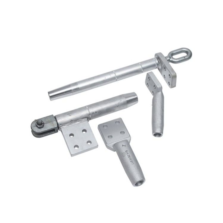
Engineers design suspension fittings to support the weight of the conductor. They protect cables from dynamic wind loads across long spans. Grip strength is vital here. However, engineers must balance grip tension against potential conductor damage. Crushing the aluminum strands causes internal resistance. You often use armor rods alongside these clamps for added protection. Armor rods distribute the mechanical stress over a wider cable area. This prevents chafing at the suspension point. You select these clamps based on the specific terrain contour and span length.
Dead-end towers or sharp line corners require strain assemblies. High tensile strength is non-negotiable for these applications. They hold the full horizontal pulling force of the conductor. Installation reality dictates your choice between bolted, compression, or wedge-type dead-ends. Bolted options offer easier field assembly for remote locations. Compression dead-ends demand heavy hydraulic presses. They create a permanent, cold-welded bond. Wedge-types self-tighten as line tension increases. Project engineers select the type based on crew access and tooling availability.
You use these items for joining conductors mid-span. We emphasize low electrical resistance for any splicing application. High resistance creates thermal hotspots. A splice must maintain at least 95% of the conductor's rated breaking strength. Weak splices risk catastrophic line drops during winter ice storms. Compression splices squeeze the aluminum and steel core together tightly. This restores original conductivity. You must ensure field crews use the exact die size for crimping. Improper crimping causes eventual pull-out failures.
Vibration dampers, grading rings, and spacer dampers fall into this category. They mitigate aeolian vibration caused by steady crosswinds. Unchecked vibration snaps conductor strands near clamps. Grading rings control the electric field distribution around insulators. Proper field distribution prevents corona loss. This protects the insulator strings from destructive arcing. Spacer dampers maintain safe distances between bundled sub-conductors. They prevent lines from clashing during short-circuit events. You deploy these protectors to guarantee long-term system stability.
Fitting Category | Primary Function | Key Engineering Focus | Common Examples |
|---|---|---|---|
Suspension | Supports vertical cable weight | Balancing grip vs. cable protection | Suspension clamps, armor rods |
Tension / Strain | Holds horizontal line tension | Maximum tensile strength (UTS) | Dead-end clamps, wedge clamps |
Connection | Joins two conductor ends | Low resistance, 95%+ breaking strength | Mid-span splices, repair sleeves |
Protective | Mitigates vibration and electric fields | Resonance tuning, corona suppression | Vibration dampers, grading rings |
You must match the Ultimate Tensile Strength (UTS) rating against expected environmental loads. Ice accumulation and gale-force winds dictate your mechanical limits. The conductor tension sets your daily operational baseline. Engineers apply strict safety factors when calculating these requirements. A fitting rated for 120kN must comfortably handle everyday loads of 40kN. You never push components to their absolute limits. Unpredictable weather events will expose any lack of safety margin. Verify these mechanical ratings through rigorous laboratory load tests.
Evaluate aluminum alloys, malleable iron, and forged steel meticulously. Each material serves specific structural purposes. Forged steel offers unmatched tensile capabilities for strain applications. Aluminum alloys provide excellent conductivity and weight reduction.
Experience Node: Galvanic corrosion destroys transmission networks silently. Mating dissimilar metals requires extreme caution from your design team. Joining a copper ground to an aluminum conductor demands bimetallic connectors. Moisture accelerates this degradation rapidly if you ignore material compatibility. A mismatched joint will oxidize, heat up, and eventually fail. You prevent this by specifying friction-welded bimetallic solutions for all cross-material junctions.
Assess conductivity strictly for any current-carrying connections. Splices and jumper terminals must carry massive amperage. High-voltage (HV) and extra-high-voltage (EHV) applications require specific corona inception voltage thresholds. Protruding bolts or sharp metal edges generate corona discharge. This phenomenon wastes energy and creates radio interference. Manufacturers must design EHV hardware featuring smooth, rounded contours. You require specialized laboratory testing to verify corona suppression at operational voltages.
Corrosion resistance determines the actual lifespan of your hardware. Standard environments require high-quality galvanization.
Hot-Dip Galvanizing: Specify zinc coating thickness according to ISO 1461. This prevents rust on forged steel components.
Salt-Fog Defense: Coastal installations require specialized epoxy coatings. Saline moisture penetrates standard galvanization quickly.
Industrial Zones: Heavy chemical environments demand acid-resistant barriers. Sulfur dioxide emissions degrade aluminum alloys severely.
UV Degradation: Any elastomeric components inside dampers must resist intense solar radiation over decades.
Demand comprehensive documentation for IEC 61284 standards. Request IEEE Std 1138 records for optical ground wire accessories. Enforce relevant ANSI/NEMA standards across all purchases. These baselines verify manufacturer claims safely. They define exact testing protocols for mechanical pull tests and thermal cycling. Following these guidelines minimizes project liability significantly. You protect your engineering firm by refusing non-compliant hardware. Suppliers must prove they understand and routinely meet these international benchmarks.
Align your network designs using heavy infrastructure manuals. The USBR transmission line guidelines offer verified safety parameters. They detail reliable clearance calculations and sag-tension limits. National grid operators publish strict localized guidelines. You must cross-reference your component specifications against these regional rules. Compliance ensures smooth regulatory approvals before energization. It also standardizes your inventory for future maintenance cycles. Institutional alignment guarantees a predictable, reliable grid deployment.
Do not accept internal manufacturer claims blindly. Advise your procurement buyers to request independent data. Verify component integrity through a structured documentation review:
Request formal type test reports from initial product design phases.
Review routine test logs from recent manufacturing batches.
Demand sample test data drawn directly from your specific order.
Verify the accreditation status of the independent testing laboratory.
Cross-check the submitted test dimensions against your requested technical drawings.
Difficult terrains complicate installation tooling severely. Heavy hydraulic presses for compression fittings pose logistical nightmares on steep mountainsides. Transporting heavy generators requires helicopter lifts in remote regions. Bolted alternatives often mitigate terrain challenges effectively. They allow crews to use standard hand tools. However, bolted connections require precise torque management. Assess your crew's access and skill levels carefully. You choose the transmission hardware fitting based on field reality, not just theoretical lab performance.
Structural loosening happens gradually over time. The coefficient of thermal expansion between the conductor and the transmission hardware fitting must pair correctly. Mismatched metals expand differently under intense summer heat. They contract unevenly during winter freezes. This constant thermal cycling causes micro-slippage. Connections eventually loosen, increasing electrical resistance. This generates localized heating, leading to complete joint failure. You mitigate this risk by selecting clamp alloys matching the conductor metallurgy precisely.
Field errors jeopardize reliable grids despite perfect component engineering. Improper torqueing of suspension bolts remains a common failure point. Over-tightening crushes the aluminum conductor. Under-tightening allows dangerous cable slip. Incorrect spacing of vibration dampers neutralizes their effectiveness entirely. Clear manufacturer installation manuals reduce these risks. Manufacturers should provide localized instructions for field crews. Rigorous field training ensures operational success. You must treat installation technique as a critical part of the hardware lifecycle.
Look for suppliers controlling their own core processes. Forging, casting, and machining require strict oversight. Avoid vendors simply assembling outsourced, untraceable parts. Direct control guarantees material integrity from raw ingot to finished clamp. A primary foundry understands metallurgy intimately. They adjust furnace temperatures precisely. They manage cooling rates to prevent micro-cracking in cast iron. You ensure long-term reliability by partnering directly with transparent, vertically integrated manufacturers.
Audit a supplier's Quality Assurance (QA) track record vigorously. Check their historical defect rate thoroughly. Trace raw materials back to their original mills. Inconsistent batches lead to isolated grid failures. One bad batch of suspension clamps threatens dozens of towers. Ask suppliers how they isolate and quarantine failed test samples. Review their non-conformance reporting procedures. You need a partner who values batch consistency over maximum production speed. High-quality vendors welcome QA audits openly.
Request detailed technical drawings initially. Reviewing CAD files reveals engineering maturity. Conduct a pilot installation next. Test the hardware on a small training span. Request localized references for similar environmental deployments. Ask current clients about rust or slip issues over a five-year period. Bulk procurement requires proven reliability beforehand. Never commit to large-scale orders without touching the physical samples.
Evaluation Criteria | Importance Weight | What to Look For |
|---|---|---|
Vertical Integration | High | In-house forging, casting, and CNC machining capabilities. |
Testing Transparency | Critical | Readily available IEC/IEEE lab reports and routine batch logs. |
Environmental Customization | Medium | Ability to adjust galvanization thickness or apply epoxy coatings. |
Field Support | Medium | Clear installation manuals and tooling recommendations. |
You now understand that power fittings dictate the mechanical security of an overhead network. They govern the electrical efficiency of the transmission line entirely. Overlooking these seemingly minor components invites catastrophic failure. A properly specified clamp holds the line during devastating ice storms. A well-designed splice prevents thermal meltdowns during peak load periods. You secure the entire grid infrastructure by mastering these details.
Project managers and procurement teams must prioritize material compatibility above all. Rigorous compliance testing outranks initial component cost every time. Transparent supplier QA processes secure long-term grid stability. We encourage you to audit potential vendors rigorously. Demand independent test reports. Evaluate their forging facilities. Choose partners demonstrating engineering excellence. Your transmission network will deliver reliable power for decades when you execute these strategies.
A: A suspension fitting bears the vertical load of the conductor. It holds the cable up while allowing some movement to absorb wind forces. A tension fitting holds the horizontal strain. Engineers use tension fittings at dead-end towers or sharp corners to maintain the severe pulling force of the line.
A: You prevent galvanic corrosion by matching materials correctly. If joining dissimilar metals like copper and aluminum, you must use friction-welded bimetallic connectors. These connectors isolate the reactive metals, preventing moisture from triggering the destructive electrochemical oxidation process.
A: Manufacturers must provide ultimate tensile load testing for mechanical strength. They should supply galvanizing thickness tests to verify environmental resistance. Electrical resistance tests verify conductivity for splices. High-voltage hardware also requires corona inception tests to ensure minimal electrical loss.
A: A splicing fitting must hold at least 95% of the conductor's rated breaking strength. If it falls below this threshold, the line risks snapping under heavy ice or wind loads. Maintaining near-total breaking strength prevents catastrophic line drops during extreme weather events.


