
T: +86-18906892820
F4-19037-6#, Yiwu Intl Trade Mart, Yiwu Jinhua, Zhejiang, China (Mainland)

Views: 0 Author: Site Editor Publish Time: 2026-06-22 Origin: Site


Live power distribution switching carries extreme operational stakes. Interrupting load currents safely requires exact engineering, not guesswork. A single misstep during this process can trigger devastating electrical events. Using non-load break disconnects under load risks catastrophic arc flashes. It also causes severe equipment damage and serious compliance violations.
Selecting the proper mitigation equipment requires careful analysis. You must navigate complex voltage ratings and specific mechanism types. Planners must also account for harsh operational realities. Engineers need reliable, arc-free solutions to maintain grid stability. This guide provides utility procurement managers and electrical engineers with an evidence-based evaluation framework. We will help you evaluate, shortlist, and procure the appropriate equipment for your grid. You will learn how to align rigorous safety standards with practical field applications.
Safety and compliance (OSHA/IEEE) dictate that interrupting load current requires dedicated arc-quenching mechanisms.
Choosing between a portable load break tool and integrated load break switches depends on switching frequency and grid infrastructure footprint.
Evaluation must prioritize voltage/amperage limits (e.g., 15kV, 27kV, 38kV), dielectric strength, and hot-stick compatibility.
Opening a standard disconnect under load draws an intense electrical arc. This physical separation forces current through the surrounding air. Temperatures inside an arc flash can exceed 35,000 degrees Fahrenheit. The intense heat vaporizes solid metal components instantly. It also creates a dangerous concussive pressure wave. Standard disconnect switches lack the internal mechanisms to quench this plasma phase. They merely separate metal contacts mechanically. The electrical current continues flowing across the air gap. This ionization path sustains the arc until upstream breakers finally trip.
The cascading effects of arc flash incidents devastate utility operations. Operator injury remains the most severe and immediate risk. Line crews face severe burns, concussions, and permanent hearing loss. Unplanned downtime directly follows these explosive events. Circuits drop offline, leaving thousands of customers without power. Severe hardware degradation happens simultaneously. Surrounding insulators, crossarms, and transformers suffer permanent thermal damage. You must replace this charred infrastructure before restoring service. This reactive replacement delays grid recovery significantly.
A successful implementation strictly avoids these destructive scenarios. Predictable, arc-free circuit interruption defines true operational success. Reliable disconnection maintains overall grid stability. It also strictly adheres to established safety mandates. Operators must feel confident manipulating the equipment. We define success as safely separating energized contacts without external sparking. Properly selected tools contain the arc internally. They extinguish the plasma rapidly and safely. Grid reliability depends entirely on this controlled interruption process.
Integrated load break switches function as permanent grid fixtures. Crews install them directly at specific distribution nodes. These large devices feature built-in arc-extinguishing chambers. They operate via automated motor mechanisms or manual switch handles. Permanent installation makes them highly reliable for specific locations. They handle repeated operations without requiring external attachments.
High-frequency switching environments represent their best use case. Critical automated grid sections rely heavily on integrated switches. They perform well in substations or major feeder junctions. Operators can control many integrated switches remotely. This remote capability supports modern smart grid automation seamlessly. They isolate large fault sections within seconds.
However, integrated switches carry significant operational limitations. High capital expenditure prevents widespread deployment across every pole. Utilities cannot afford to install them at every single disconnect point. They also lack mobility across the broader distribution network. Once installed, they only protect that specific physical location. Routine line maintenance often happens far away from these permanent nodes.
Line crews carry external arc-quenching devices called portable load break tools. Operators mount them securely to standard insulated hot sticks. These lightweight devices travel directly in utility fleet vehicles. Crews attach them temporarily across standard cutout switches. The internal mechanism bypasses the current through the tool itself. The tool then extinguishes the arc internally during separation.
Widespread, routine maintenance creates the ideal use case. Crews deploy them on traditional cutout switches and standard disconnects. Permanent load break switches are often cost-prohibitive for these remote rural lines. Field teams need a flexible solution for daily repairs. This mobility allows a single crew to safely operate multiple cutouts daily. They handle transformer changeouts, capacitor maintenance, and routine line repairs.
The core advantage lies in immediate infrastructure transformation. A portable load break tool transforms existing non-load break infrastructure safely. It turns basic switches into safe switching points flexibly. Utilities avoid replacing thousands of existing cutouts. They instead equip their crews with reliable portable devices. This approach maximizes safety across vast geographical territories.
Solution Category Comparison Chart | ||
Evaluation Category | Integrated Load Break Switches | Portable Load Break Tools |
|---|---|---|
Installation Type | Permanent node fixture | Temporary, carried by crews |
Mobility | Zero mobility | Highly mobile across entire grid |
Capital Investment | High upfront hardware costs | Economical fleet deployment |
Primary Application | Automated junctions, substations | Routine line maintenance, rural disconnects |
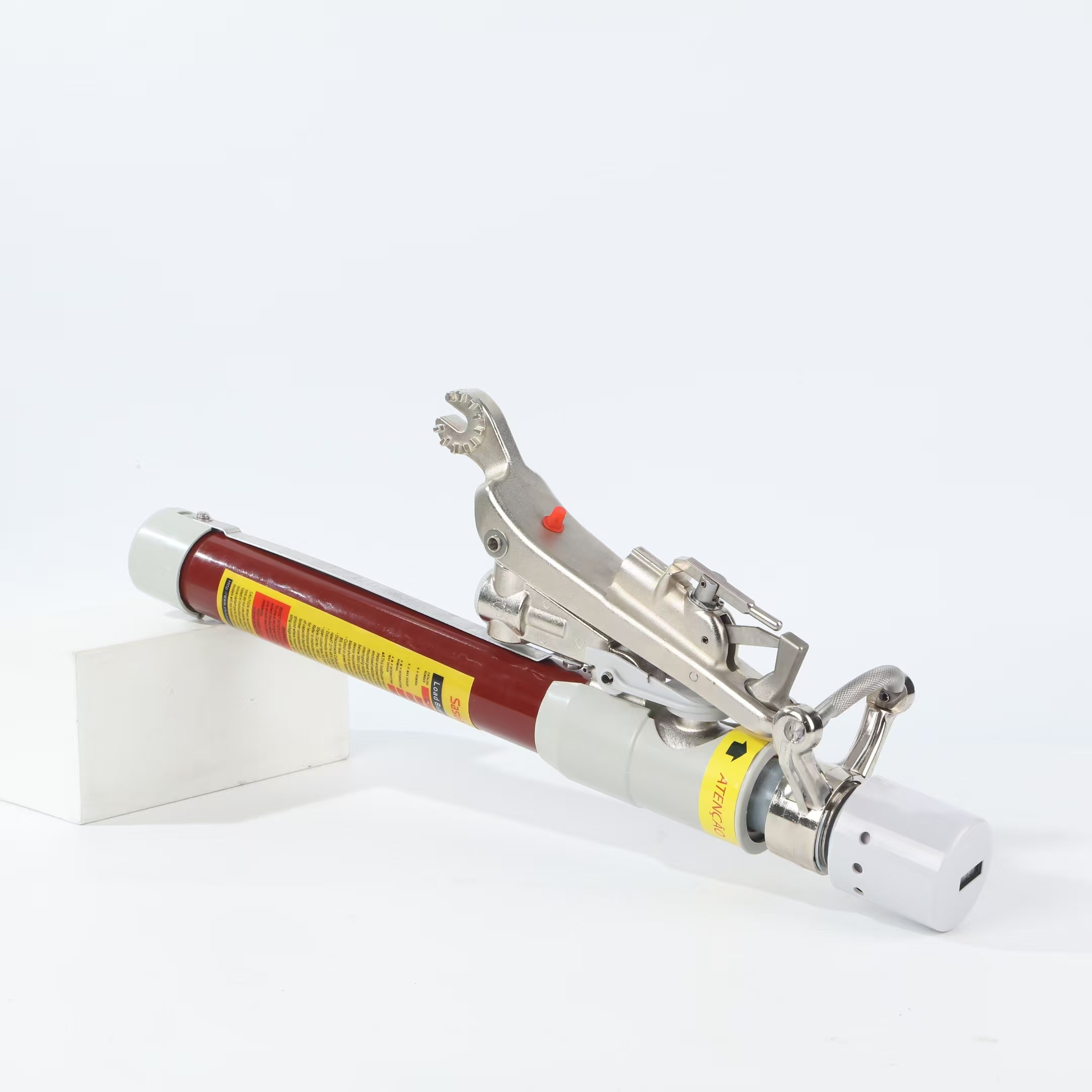
Electrical ratings form the absolute foundation of tool safety. You must never exceed the manufacturer's maximum design voltage. Deploying a 27kV-rated tool on a system experiencing higher transient potential creates extreme danger. This mismatch guarantees a critical failure risk. Transients can easily puncture inadequate dielectric materials. Operators must verify peak circuit voltages before every single operation. Mismatched ratings lead directly to internal flashovers.
Engineers must carefully match continuous and interrupting capabilities. The tool must handle the circuit's actual peak loads securely. Amperage limits determine the internal contact design. Attempting to interrupt 900 amps using a 600-amp rated tool destroys the internal vacuum bottle. Procurement teams must audit their system's maximum fault currents. You must select load break tools exceeding these regional maximums. Adequate overhead margin prevents catastrophic mechanical binding during operations.
You must rigorously evaluate the internal quenching technology. Different tools utilize varying arc interruption methods. Vacuum bottles dominate modern designs due to their high reliability. They draw the arc inside a sealed vacuum chamber. The lack of air instantly suffocates the electrical plasma. Some legacy systems utilize SF6 gas or solid dielectric materials. Vacuum systems generally require less frequent environmental monitoring.
Focus your evaluation on mechanical reliability and reset mechanisms. Crews prefer auto-resetting tools for faster field operations. Manual reset designs require extra steps between individual switching events. Auto-resetting internal springs speed up multi-phase line clearing significantly. Visual indicators also play a critical safety role. Tools must provide clear, visible confirmation of a successful break. Operators need physical proof indicating separated internal contacts.
Assess tool weight and physical balance meticulously. Line crews must manipulate these devices under challenging physical conditions. They operate them at the far end of extended fiberglass hot sticks. Adverse weather amplifies these ergonomic challenges significantly. High winds and heavy rain make heavy tools nearly impossible to control. Lighter tools reduce operator fatigue and prevent accidental slips.
Check physical compatibility against your existing utility cutouts. Distribution grids often feature multiple brands of disconnect switch hooks. The tool's attachment probe must securely latch onto your specific hardware. An improper fit causes the tool to dislodge under tension. Test the tools physically against your most common switchgear models. Universal compatibility reduces the need for multiple specialized tools.
Safety compliance requires strict adherence to documented global standards. Utilities cannot rely on vendor promises alone. You must verify actual certification documents thoroughly.
Regulatory Baselines: Ensure the tool meets or exceeds relevant IEEE standards. ANSI and IEC certifications govern high-voltage testing and arc interruption criteria. These frameworks dictate strict performance baselines. Devices must pass rigorous short-circuit tests to earn these certifications. Procurement teams should reject uncertified equipment immediately.
Dielectric Integrity: Look for tools offering verifiable dielectric strength. High-quality resins and fiberglass bodies protect the operator effectively. This insulation prevents dangerous surface tracking and sudden flashovers. The material must repel water and resist carbon buildup. Compromised dielectric surfaces turn the tool into a conductive hazard.
Comprehensive Documentation: Demand transparent testing data from every manufacturer. Request official cycle-life ratings and detailed breakdown reports. Official installation and operation manuals must accompany every delivered unit. Clear documentation ensures correct field application. Line crews reference these manuals directly when developing internal safety protocols.
Independent laboratory testing provides the highest level of assurance. Do not accept in-house manufacturer testing as the sole proof. Reputable brands gladly provide third-party validation reports. These reports confirm the tool handles its maximum rated capacities safely.
Procuring the hardware only represents the first deployment step. Implementation introduces unique human and mechanical variables. You must proactively manage these adoption risks.
Crew Training Bottlenecks: A tool is only as safe as the operator using it. You must outline strict standard operating procedures (SOPs) immediately. Hands-on training ensures proper physical alignment and secure attachment. Incorrect attachment angles cause the tool to slip off energized lines. Dedicate full training days to dry-run operations.
Maintenance Neglect: Mechanical binding presents a severe operational risk over time. Internal components suffer wear during repeated arc interruptions. Acknowledge the serious risk of hidden vacuum loss. If the internal bottle loses its vacuum, the tool will explode upon deployment. Scheduled mechanical lubrication prevents internal springs from seizing.
Inspection Protocols: Highlight the absolute necessity of daily visual inspections. Crews must check the fiberglass housing for deep scratches or carbon tracks. Mandate scheduled dielectric field testing annually. Specialized test equipment verifies the tool's internal insulation remains intact. Quarantine any tool failing these basic visual or electrical checks.
Adoption fails when organizations ignore operator feedback. Encourage line crews to report binding mechanisms immediately. Create a seamless repair pipeline for damaged equipment. Replace worn tools proactively before they fail under load.
Strategic shortlisting requires a clear understanding of your specific grid footprint. Start by auditing your existing electrical infrastructure comprehensively. Map the exact voltage classes utilized across your distribution poles. Identify the specific cutout switch brands currently installed. This audit prevents purchasing physically incompatible equipment. Documenting your system's peak fault currents dictates your required interruption ratings.
Next, define the physical operating environment accurately. Factor in regional weather extremes and seasonal temperature variations. Coastal utilities face salt fog, demanding superior dielectric housing materials. High-altitude grids experience lower air density, affecting overall insulation ratings. Evaluate your crew mobility and the frequency of daily use. High-frequency usage demands tools boasting superior cycle-life endurance.
Instruct buyers to request definitive proof from shortlisted vendors. Demand specific cycle-testing data matching your expected load conditions. Ask for transparent maintenance schedules and component replacement intervals. Require physical field demos from vendors before finalizing decisions. Let your most experienced linemen test the tools on energized training lines. Their tactile feedback proves invaluable.
Finally, transition smoothly into the procurement phase. Advise consulting heavily with technical sales engineers. Verify precise compatibility with your specific grid requirements before issuing a purchase order. Establish a clear warranty and repair agreement upfront. Proper technical alignment guarantees a smooth, safe rollout across your utility fleet.
Investing in the correct load break devices represents a non-negotiable safety priority. Modern utility risk management demands reliable, proven arc-quenching technologies. Relying on standard disconnects under load invites unacceptable disaster. Proper equipment protects your frontline personnel and preserves your expensive grid hardware. It ensures you maintain strict regulatory compliance effortlessly.
The right choice balances upfront capital alongside operational flexibility. You gain uncompromising operator safety without overspending on permanent node fixtures. Portable solutions offer incredible mobility across vast distribution networks. Careful evaluation of voltage limits, ergonomics, and dielectric strength guarantees operational success. Your crews deserve the highest level of mechanical protection available.
Take immediate action to upgrade your line crew equipment today. Download our comprehensive technical spec sheets to compare voltage ratings. Review our extensive product catalog for high-voltage solutions tailored to your environment. Contact our engineering support team for a personalized system compatibility assessment. Secure your grid and protect your operators with proven technology.
A: The exact difference lies in the presence of an arc-quenching mechanism. A load break switch contains internal components, like vacuum bottles, designed to safely extinguish electrical arcs. A standard disconnect switch only separates metal contacts mechanically. Opening a disconnect switch under load draws a dangerous, uncontained electrical arc.
A: Yes, but strictly within the manufacturer's specified weather ratings. High-quality tools feature specialized dielectric materials that resist water tracking. However, heavy rain compromises insulation limits. Operators must always verify the tool's specific dielectric limits and adhere to internal utility safety protocols regarding adverse weather switching.
A: A standard tool typically handles between 1,500 and 2,000 operational cycles before requiring major maintenance. However, high-amperage interruptions degrade internal contacts much faster. Utilities must mandate tracking individual tool usage closely. Regular daily visual inspections and scheduled dielectric testing remain critical regardless of the cycle count.
A: No, they are not completely universal. While many feature highly adaptable designs covering standard industry models, specific dimensional checks remain mandatory. Different cutout brands utilize varying hook shapes and pull-ring sizes. Always physically test the tool against your utility's specific switchgear models to ensure a secure latch.


