
T: +86-18906892820
F4-19037-6#, Yiwu Intl Trade Mart, Yiwu Jinhua, Zhejiang, China (Mainland)

Views: 112 Author: Site Editor Publish Time: 2026-10-15 Origin: Site


Opening a standard disconnect switch while current is flowing presents severe safety hazards. You risk catastrophic arc flashes, equipment vaporization, and fatal operator injuries. Utilities, industrial facilities, and electrical contractors frequently face a major operational bottleneck. They need to isolate circuits for maintenance without shutting down entire upstream systems. This becomes especially challenging when existing infrastructure lacks integrated load-break capabilities. A portable load bust tool acts as an engineered solution. It safely interrupts load current on compatible disconnect switches, cutouts, and power fuses. This device bridges the gap between operational efficiency and strict safety compliance. We will look at how these devices work, mechanical compatibility requirements, and the mandatory safety standards you must follow in the field.
The Verdict: Yes, a load bust tool can be used to open disconnect switches under load, provided the switch is mechanically compatible (equipped with load-break hooks/rings) and the load does not exceed the tool’s rated capacity.
Safety Imperative: Standard disconnect switches are isolators, not interrupters; attempting to "throw live disconnects" under load without a specialized load bust tool or integrated arc-extinguishing mechanism violates safety standards and risks explosive arc flash incidents.
Limitation Awareness: A standard load bust tool is designed strictly for load current interruption, not fault current (short circuit) interruption or load pick-up.
Cost vs. Utility: Utilizing portable load bust tools offers a highly scalable, cost-effective alternative to retrofitting entire distribution networks with permanent load break switches.
Standard disconnect switches function strictly as isolators. Engineers design them to provide visual confirmation of a de-energized circuit. When you look up at a pole or into a switchgear cabinet, you see the physical air gap. These devices lack internal arc-quenching mechanisms. You cannot use them to interrupt active current flow. Their primary purpose is protecting maintenance crews by creating a visible physical break in the circuit. Operators must remove the load using downstream breakers before opening these isolators. Operating them under load invites immediate and catastrophic failure. We often see older grid infrastructure relying heavily on these simple blade-and-jaw configurations. They are robust for carrying current but highly dangerous if operated incorrectly.
Integrated load break switches operate differently. Manufacturers build these devices to safely extinguish electrical arcs internally. They feature built-in mechanisms designed for continuous current interruption. Some utilize specialized arc chutes to stretch and cool the arc as the blade opens. Others employ vacuum bottles to prevent arc formation entirely by breaking the circuit in an oxygen-free environment. Certain models use ablative materials generating de-ionizing gases. These built-in features allow operators to open the switch while current flows normally. They require no external devices for safe operation. You simply pull the handle or operate the hot stick, and the internal components handle the arc suppression automatically.
Common Arc Extinguishing Methods in Electrical Switching
Extinguishing Method | Mechanism of Action | Typical Application |
|---|---|---|
Ablative Material | Vaporizes to create high-pressure de-ionizing gas | Portable interruption tools, cutouts |
Vacuum Bottle | Separates contacts in an oxygen-free chamber | Integrated load break switches, reclosers |
Arc Chutes | Stretches and cools the arc across metal plates | Low voltage disconnects, air circuit breakers |
SF6 Gas | Quenches arc using highly electronegative gas | High voltage transmission switches |
Field operators must identify switch capabilities quickly before taking any action. The equipment nameplate provides this information. You should look for a specific Horsepower (HP) rating. A switch carrying an HP rating generally possesses the capability to break motor loads safely. It functions as a load break device. Conversely, a switch lacking this rating acts strictly as an isolator. Many isolators explicitly state "non-load break" on their manufacturing plates. You must use a load bust tool to open these non-rated isolators safely. Never guess a switch's capability based on its physical size or age. Always verify the engineering data stamped on the side.
Opening a non-load break switch under load violates basic physical laws of electricity. Current resists interruption. As the switch blade separates from the contact jaw, electricity jumps the air gap. This creates an electrical arc. The surrounding air rapidly ionizes into a conductive plasma state. Temperatures inside this plasma can reach 35,000 degrees Fahrenheit.
This extreme heat vaporizes copper contacts instantly. Copper expands 67,000 times its original volume during vaporization. This rapid expansion creates a concussive blast wave. We call this event an arc flash. An arc flash destroys equipment, blows cabinet doors off hinges, and causes fatal burns. Throwing live disconnects directly violates OSHA and NFPA 70E safety standards. You must never attempt this action without proper interruption equipment.
A portable interruption device functions as a temporary, parallel switch. The operator attaches the device using an insulated hot stick. The upper anchor hooks onto the disconnect switch frame. The lower connection engages the switch blade pull ring. The operator pulls downward firmly. This action opens the main switch blade.
Current immediately diverts from the opening blade into the portable tool. The tool maintains a continuous electrical path during this initial movement. The external switch blade opens fully without drawing an arc in the air. The current now flows entirely through the internal mechanism of the tool. The actual circuit interruption happens safely inside the device housing.
Let's break down the exact field operation sequence:
Inspect the tool to ensure the internal mechanism is fully reset and locked.
Mount the tool securely onto an approved, tested fiberglass hot stick.
Position the upper hook of the tool over the stationary attachment point on the switch jaw.
Guide the lower pull-ring hook of the tool into the eyelet of the movable switch blade.
Apply a smooth, continuous downward force on the hot stick to pull the switch blade open.
Continue the downward motion until the internal mechanism trips and interrupts the circuit.
Remove the tool from the switch and reset it on the ground before the next operation.
The internal operation relies on precise mechanical timing. As the operator continues pulling downward, an internal spring mechanism compresses. Reaching a specific tension point, the spring releases violently. This snaps the internal contacts open at high speed. An arc forms inside the tool chamber.
The chamber contains a specialized trailer and liner system. These components consist of ablative materials. The heat of the arc vaporizes a thin layer of this material. This vaporization generates a high-pressure, de-ionizing gas. The gas blasts through the arc path, cooling and extinguishing it instantly. A muffler system safely vents the expanding gases away from the operator. The entire process takes milliseconds.
You must understand the specific operational limits of these devices. A standard portable interruption tool handles load breaking only. It interrupts existing current flow safely. It does not handle fault currents or short circuits.
Furthermore, you cannot use it for load pick-up. You cannot use it to close a circuit under load. Specialized portable switch systems exist for continuous current bypass work. Mechanical jumper systems handle load pick-up tasks. You must select the exact tool engineered for your specific operational phase. Misapplying a breaking tool for a closing operation guarantees equipment failure.
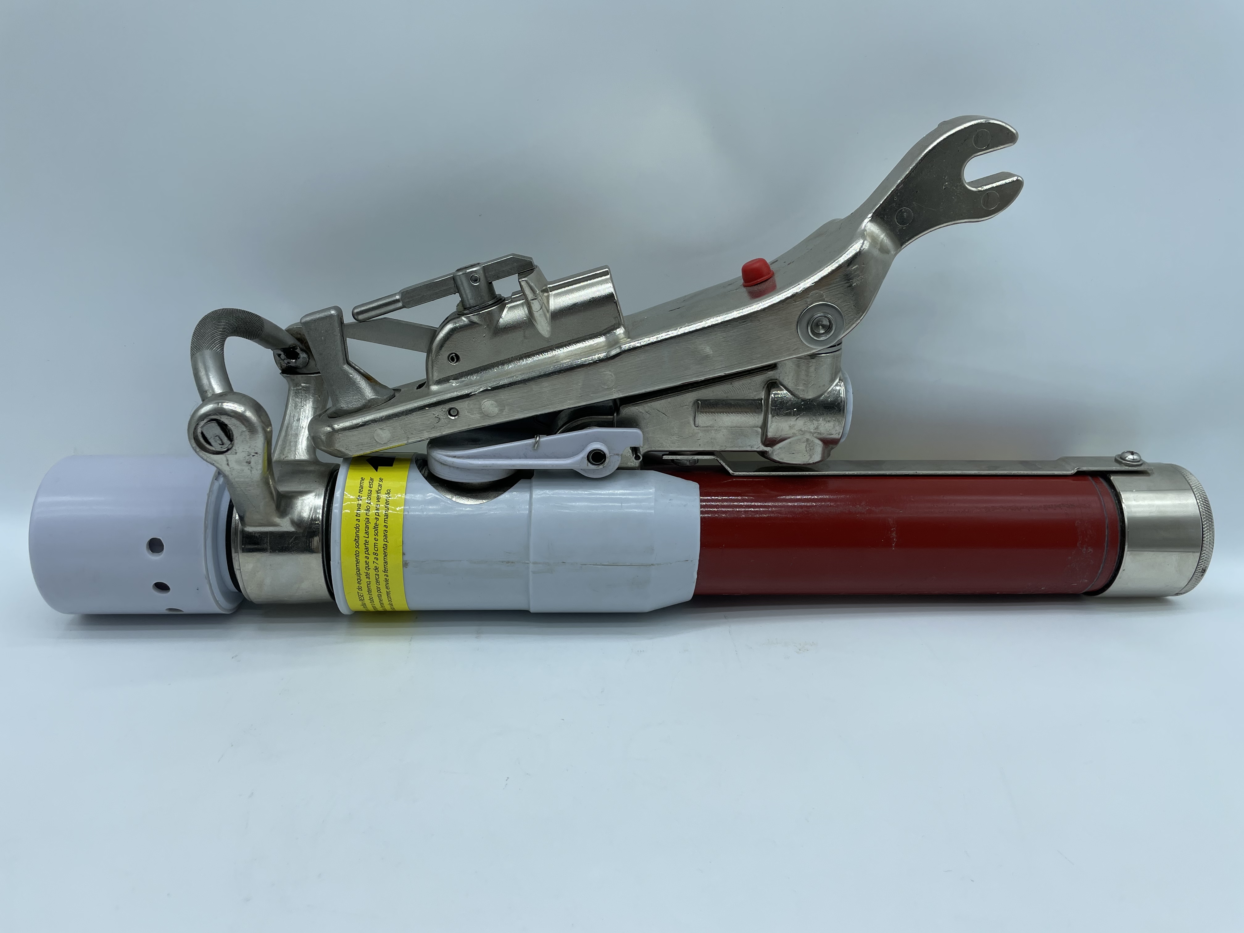
Physical compatibility determines safe operation. You cannot attach these tools to every disconnect switch. The switch must feature specific mechanical attachment points. An upper attachment hook must exist on the stationary contact jaw. A structurally sound pull ring must exist on the movable blade.
The geometric alignment matters significantly. The tool must extend fully without binding against other components. The pull angle must remain relatively straight. Severe lateral angles can snap the tool housing or bend the switch blade. Always verify the switch manufacturer explicitly supports portable interruption tool usage.
Electrical parameters dictate tool selection. You must match the tool ratings to the circuit parameters. Every tool carries a maximum voltage rating. Every tool carries a maximum continuous current rating.
Using a 15kV rated tool on a 25kV system invites dielectric breakdown. The internal gap will fail to hold back the higher voltage. The arc will restrike inside the tube. Similarly, exceeding the maximum current rating overwhelms the ablative materials. The tool will fail to generate enough gas to quench a massive arc. Always verify circuit voltage and load current before attachment.
Environmental exposure degrades switch hardware over time. Coastal installations suffer from salt spray corrosion. Industrial environments experience heavy particulate fallout. Winter conditions bring severe ice accumulation. These elements compromise the mechanical integrity of the switch.
Corroded contacts cause the blade to stick in the jaw. An operator pulling on a stuck blade creates jerky, unpredictable movements. Smooth operation remains mandatory for safe current diversion. A violently jerking blade can break the tool attachment or fail to divert current properly. You must inspect the switch for physical integrity before attempting operation. Stiff or heavily contaminated blades require maintenance before tool application.
Operators must recognize hard stop conditions. Never proceed if you identify any of the following situations:
The switch lacks proper attachment hooks or pull rings.
The switch blade appears bent, cracked, or structurally compromised.
The system is experiencing a known fault or short circuit condition.
The circuit voltage exceeds the maximum nameplate rating of the tool.
The load current exceeds the maximum interruption rating of the tool.
Environmental conditions exceed the dielectric ratings of the fiberglass housing.
The tool itself shows signs of physical damage or lacks recent testing tags.
Facility managers and utility engineers face a common infrastructure challenge. They must isolate circuits safely while minimizing downstream outages. A successful deployment meets three strict criteria. First, it must result in zero safety incidents. Second, it must minimize operational downtime. Third, it must adhere to strict budgetary constraints. Evaluating the right approach requires comparing portable tools against permanent switch upgrades.
Replacing standard disconnects with integrated load break switches requires significant capital expenditure. You must purchase expensive hardware. You must schedule extensive facility outages for installation. You must pay specialized labor rates for the retrofitting process.
Equipping crews with portable tools represents a tooling expenditure. The upfront cost remains drastically lower. You avoid massive installation outages. The portable tool achieves the exact same safety outcome during maintenance operations. The cost-to-outcome ratio heavily favors the portable approach for existing infrastructure.
Portable tools offer unmatched scalability across large networks. A single utility crew can carry one tool in their truck. That single device can service hundreds of compatible disconnects across an entire grid.
Industrial campuses benefit similarly. Maintenance personnel can isolate different building sectors using one standardized tool. You do not need to upgrade every isolation point in the facility. This flexibility allows organizations to direct capital toward infrastructure expansion rather than redundant switch upgrades.
Permanent load break switches offer distinct conveniences. They remain permanently installed and always ready. Operators need no special attachment tools to open them. They reduce the physical steps required during an emergency isolation.
However, permanent switches carry higher maintenance overhead. Their internal mechanisms require periodic inspection and lubrication. Portable tools require maintenance too, but you service them in a controlled shop environment. You must weigh the convenience of permanent switches against their upfront installation costs and field maintenance requirements.
Comparison Between Portable Interruption Tools and Permanent Switch Upgrades
Evaluation Criteria | Portable Interruption Tools | Permanent Load Break Switches |
|---|---|---|
Initial Capital Investment | Low | High |
Installation Downtime | None | High |
Scalability | Excellent | Poor |
Maintenance Environment | Controlled shop environment | Field environment |
Speed of Operation | Moderate | Fast |
Best Application Scenario | Expansive networks, infrequent operation | High-frequency operation nodes |
Electrical safety regulations mandate strict adherence to safe work practices. OSHA 1910.269 governs power generation, transmission, and distribution work. It explicitly prohibits opening non-load break devices under load without approved interruption equipment.
NFPA 70E establishes guidelines for electrical safety in the workplace. It defines arc flash boundaries and hazard risk categories. Using a portable interruption device aligns directly with these regulatory frameworks. It eliminates the open-air arc hazard, thereby reducing the risk category of the switching task. Compliance requires utilizing the right tool for the specific electrical load.
Using an interruption tool does not eliminate personal protective equipment requirements. The tool mitigates the primary arc flash risk. However, mechanical failures or operator errors remain possible. You must wear appropriate Arc Flash PPE based on the calculated incident energy of the equipment.
Standard operating procedures mandate specific gear. Operators must wear arc-rated clothing. They must utilize proper face shields and safety glasses. They must wear voltage-rated rubber insulating gloves with leather protectors. They must operate the tool using a tested, insulated hot stick. Never operate these devices using bare hands or unrated extension poles.
Safety auditors evaluate equipment reliability based on strict engineering standards. IEEE and ANSI/NEMA provide the testing frameworks for these devices. Manufacturers must prove their tools can interrupt specific currents across hundreds of test cycles.
Auditors look for certification marks indicating compliance with these standards. They verify the dielectric strength of the fiberglass housing. They review the mechanical endurance of the internal springs. Utilizing non-certified or counterfeit tools exposes organizations to massive liability. Always source equipment from manufacturers who publish their ANSI/IEEE testing data openly.
Improper operation represents the highest risk factor. An untrained operator might fail to attach the tool securely. They might pull at a severe lateral angle, damaging the switch. The most dangerous error involves failing to reset the tool before use.
If an operator does not fully reset the internal mechanism, the contacts remain open. The tool will not divert current. Pulling the switch blade will immediately draw a deadly open-air arc. Mitigation requires rigorous, documented hands-on training. Organizations must mandate periodic recertification. Operators must practice the reset and attachment sequence on de-energized training mounts.
Using a degraded tool invites catastrophic failure. The internal ablative materials deplete slightly with every operation. The exhaust mufflers accumulate carbon deposits. The fiberglass housing can suffer micro-fractures or moisture ingress.
Mitigation demands strict lifecycle management. Operators must perform daily visual inspections before use. Maintenance departments must implement routine dielectric testing of the housing. You must track the exact number of field operations. Manufacturers specify exact rebuild intervals based on operation counts. You must schedule internal component replacements, such as new contacts or mufflers, strictly according to these intervals.
Here is a standard field inspection checklist before operating the tool:
Verify the tool is fully reset and the latch is engaged.
Inspect the fiberglass housing for cracks, deep scratches, or tracking marks.
Check the exhaust muffler for excessive carbon buildup or blockages.
Ensure the upper hook and lower pull ring move freely without binding.
Confirm the operation counter is within the manufacturer's safe limit.
Operators face severe risks if they misidentify switch capabilities. Attempting to use a portable tool on an incompatible switch causes mechanical binding. Conversely, guessing that a standard isolator can break a load leads to arc flash incidents.
Mitigation requires comprehensive asset management. Facilities must standardize equipment labeling across the entire grid. You must verify HP ratings on all nameplates and ensure they remain legible. Organizations should maintain accurate geographic information systems. Facility asset databases must clearly indicate which switches require portable tools and which possess integrated load break capabilities.
A portable interruption device provides a highly effective method for isolating circuits. It represents a safe and compliant approach for opening standard disconnect switches under load. Success depends entirely on mechanical compatibility and strict adherence to rated voltage and current limits. When used correctly, it eliminates the catastrophic risks associated with open-air electrical arcs. Organizations managing expansive networks of standard disconnects should prioritize portable tools. They offer massive scalability and reduce capital expenditures significantly. Conversely, you should recommend permanent load break switches for high-frequency operation points. Critical grid nodes requiring immediate, tool-free isolation benefit most from permanent hardware upgrades.
Audit your existing disconnect switch infrastructure immediately to verify hook and pull-ring compatibility.
Assess your current load profiles to ensure they fall within the maximum interruption ratings of standard portable tools.
Inspect all field switches for severe environmental degradation, corrosion, or mechanical binding.
Update facility asset databases to clearly label all non-load break isolators requiring specialized tooling.
A: Opening a standard disconnect under load draws a massive electrical arc in the open air. This rapidly ionizes the air into plasma, causing an explosive arc flash. The extreme heat vaporizes copper contacts, destroys the equipment, and can cause fatal burns to the operator.
A: A disconnect switch carrying a specific HP rating is generally designed to break motor loads safely on its own. If the switch lacks an HP rating or is labeled "non-load break," it is strictly an isolator. You must use a specialized interruption tool to open it under load.
A: No. Standard portable interruption tools are engineered strictly for breaking load current. They cannot handle load pick-up or continuous current bypass. Attempting to close a circuit using a standard breaking tool will cause catastrophic mechanical and electrical failure.
A: The switch must feature specific attachment points. It requires a sturdy upper attachment hook on the stationary jaw and a structurally sound pull ring on the movable blade. The geometry must allow the tool to extend fully without binding or severe lateral angles.
A: An interruption tool creates a temporary parallel path to safely extinguish an arc when opening a circuit. A mechanical jumper provides a continuous current bypass path. Jumpers are used to maintain power flow around a work area or handle load pick-up tasks.
A: Operators must perform visual inspections before every single use. Maintenance departments must conduct routine dielectric testing annually. Complete rebuilds, including replacing contacts and ablative liners, depend on the number of operations performed. You must track operation counts and follow the manufacturer's specific rebuild schedule.
A: No. These tools are designed exclusively for normal load current interruption. They lack the mechanical strength and arc-quenching capacity to safely interrupt massive fault currents or short circuits. Attempting to clear a fault with this tool will result in explosive failure.


