
T: +86-18906892820
F4-19037-6#, Yiwu Intl Trade Mart, Yiwu Jinhua, Zhejiang, China (Mainland)

Views: 148 Author: Site Editor Publish Time: 2026-07-11 Origin: Site


Physical, visible isolation remains a non-negotiable requirement for safeguarding personnel and equipment during grid maintenance. When operators work on live networks, they need absolute certainty regarding system de-energization. Routine switching differs significantly from off-load isolation within high voltage (HV) and medium voltage (MV) architectures. Breakers handle the dynamic fault clearing, but they do not provide the visible air gap necessary for human safety. This is where proper isolation equipment becomes critical.
This article aims to provide a comprehensive technical and commercial framework for power systems engineering. You will learn how to evaluate, size, and select the correct device based on operational constraints, environmental realities, and specific project budgets. We will explore mechanism types, deployment environments, and strict selection criteria. Understanding these factors ensures your power system remains safe, compliant, and highly reliable during all phases of operation.
A disconnector switch guarantees off-load, visible isolation; it is not designed to interrupt fault or load currents.
Selection between center-break, double-break, and pantograph models depends strictly on substation spatial limits and voltage classifications.
Specifying an outdoor disconnector switch requires prioritized evaluation of creepage distance, ice-breaking capacity, and anti-corrosion treatments.
Procurement should anchor on verifiable compliance with IEEE C37.32 or IEC 62271-102 standards, emphasizing mechanical endurance and short-time withstand current.
The primary objective of a disconnector switch is providing a verifiable, visible air gap. This gap ensures absolute safety during localized grid maintenance. Engineers rely on this physical break to confirm a circuit holds no live voltage. Without it, maintenance crews risk fatal exposure to accidental re-energization.
Beyond safety, these devices serve a vital secondary objective. They enable substation busbar routing and transferring. Network operators use them to reconfigure grid topology. They isolate specific transformer bays or bus sections for service while keeping the broader network energized.
Many new engineers confuse the roles of breakers and disconnectors. You must understand their fundamental differences to design safe systems.
A circuit breaker acts as an on-load device. It actively extinguishes arcs and clears massive electrical faults. Breakers feature complex arc-chuting mechanisms, vacuum bottles, or SF6 gas chambers designed to quench plasma instantly. They handle massive energy safely.
Conversely, a disconnector remains strictly an off-load device. It lacks any arc-chuting capabilities. You must operate it only when the circuit is already de-energized by a breaker. Opening a disconnector under active load draws a catastrophic, sustained arc. This arc can melt the contacts, destroy the surrounding equipment, and cause severe operator injury.
Power lines often retain dangerous residual charges even after disconnection. Parallel energized lines can also induce dangerous voltages through capacitive coupling. For these reasons, manufacturers frequently pair disconnectors with integral earth switches.
The earthing switch mechanically grounds this residual charge. Operators close the earth switch only after fully opening the main disconnector contacts. This tandem operation creates a fully safe work zone. It guarantees all stray voltages route directly to the earth grid.
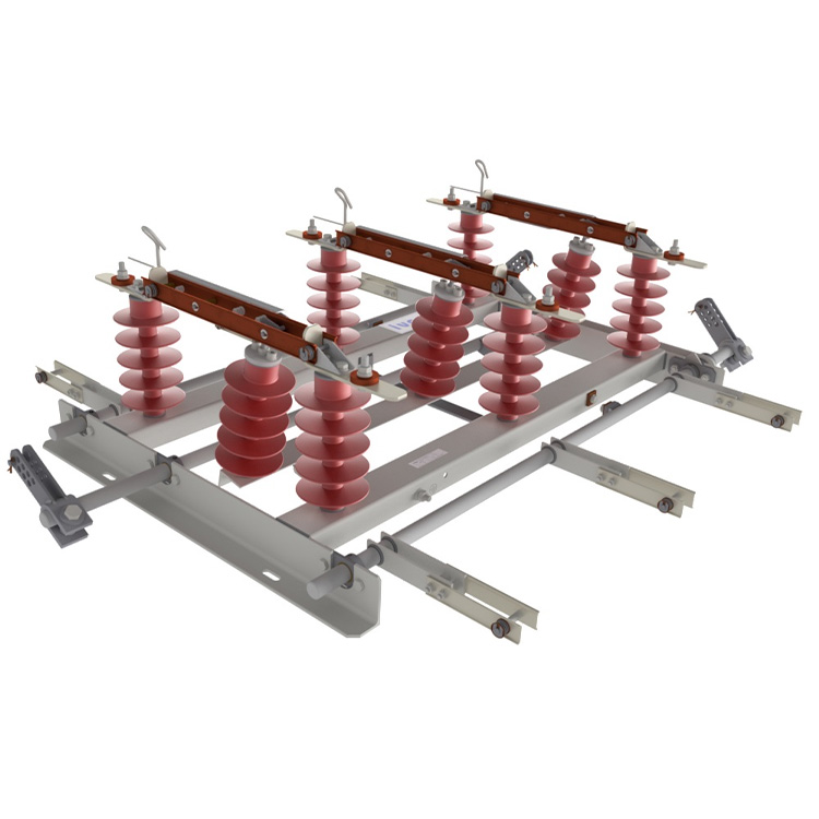
Substation designers must choose the right mechanical configuration. Your choice depends directly on available land footprint and system voltage class.
Center-break configurations feature two rotating insulators per phase. These insulators turn in opposite directions to part the contacts squarely in the middle. The mechanism is straightforward, reliable, and easy to maintain.
You will find center-break models best for standard MV and HV applications. They require adequate phase spacing because the blades swing outward during operation. They offer a highly cost-effective and mechanically simple solution for spacious, traditional substations.
Double-break configurations utilize three insulators per phase. The central insulator rotates. As it turns, it bridges or breaks connection between two stationary contacts located on the outer insulators.
These models work best for harsh environments. They excel on high-voltage lines requiring exceptional mechanical stability. Because the contact points sit on stationary posts, double-break switches handle heavy wind and ice loads far better than center-break designs.
Pantograph configurations deploy a vertical reach mechanism. The switch arms extend upward to grasp a contact suspended on an overhead busbar. This vertical motion dramatically minimizes the horizontal footprint of the switchgear bay.
You should specify pantograph models for ultra-high voltage (UHV) networks. They also suit highly congested HV substations. While they demand higher capital investment and complex maintenance, the immense savings in substation footprint space easily justifies the premium.
Mechanism Type | Insulators per Phase | Primary Motion | Best Application Scenario |
|---|---|---|---|
Center-Break | Two | Horizontal Rotation | Spacious MV/HV substations; budget-conscious projects. |
Double-Break | Three | Central Rotation | High wind/ice zones; requires high mechanical stability. |
Pantograph | One (Base) | Vertical Extension | UHV networks; heavily congested urban substations. |
Outdoor environments subject electrical infrastructure to brutal conditions. When you specify an outdoor disconnector switch, you must prioritize environmental resilience over pure electrical performance.
Environmental Degradation Constraints: You must assess the raw materials used. Galvanized steel bases, copper alloy conducting arms, and silver-plated contacts face constant attack. UV radiation, salt-fog near coasts, and industrial pollution accelerate oxidation. Specify strict anti-corrosion treatments. Ensure the silver plating thickness on contacts meets standards to prevent localized heating.
Insulator Selection: Choosing between porcelain and polymeric (silicone rubber) insulators requires care. Porcelain offers proven longevity and exceptional mechanical rigidity. However, silicone rubber provides superior hydrophobicity. It repels water and prevents conductive tracks in highly polluted areas. Furthermore, polymeric insulators offer better flexibility, making them the preferred choice in zones with strict seismic requirements.
Ice and Wind Loading: Severe weather threatens switch operation. Ice accumulation can freeze linkages solid. High winds can warp contact arms. You must verify the specific mechanical terminal load ratings. The switch must possess sufficient motorized torque and ice-breaking capacity to shatter frozen layers during emergency operations.
Indoor deployments face entirely different challenges. Here, space is the ultimate premium.
Space utilization within switchgear cubicles drives indoor design. Manufacturers condense the switch footprint to fit inside standard metal-clad panels. You must account for safe clearance distances within these tight confines.
Furthermore, indoor switches rely heavily on epoxy resin insulators. These cast-resin components provide excellent dielectric strength in tight spaces. You must also ensure the switch integration aligns with the switchgear's internal arc classifications. A failure inside a sealed metal cabinet generates massive pressure; the switch design must not compromise the enclosure's pressure-relief pathways.
Selecting the right equipment prevents operational failures and safety incidents. You must follow a rigid, data-driven evaluation framework.
Determine System Voltage and Current Ratings: Match the rated voltage (Ur) and rated normal current (Ir) exactly to your system maximums. Avoid unnecessary specification inflation. Over-specifying voltage ratings heavily inflates equipment size and project costs without adding tangible safety benefits.
Calculate Short-Time Withstand Current (Ik): Evaluate the switch’s ability to survive faults. A downstream short circuit sends massive currents through the switch before the breaker trips. The disconnector must remain mechanically intact and firmly closed during this extreme electro-dynamic stress.
Select Operating Mechanisms (Drive Types): Decide between manual and motorized drives.
Manual Drive: Sufficient for infrequent operations in localized MV networks. They rely on human operators turning a crank.
Motorized Drive: Essential for remote SCADA integration. Motorized drives enable automated fault isolation and serve as the backbone for larger HV linkages.
Implement Safety and Interlocking Systems: You must mandate fail-safes. These interlocks prevent the disconnector from opening under load or closing when the earthing switch is active. Mechanical interlocks use physical keys and cams. Electromagnetic interlocks use logic circuits tied to the breaker's status. Modern systems often blend both for redundant safety.
Parameter | Symbol | Primary Importance | Common Mistake |
|---|---|---|---|
Rated Voltage | Ur | Defines insulation levels and phase spacing. | Over-specifying beyond regional grid standard tiers. |
Rated Normal Current | Ir | Determines contact size and thermal capacity. | Ignoring future load-growth expansions. |
Short-Time Withstand | Ik | Ensures mechanical survival during faults. | Failing to match the upstream breaker's clearing time. |
Even the best-engineered switch will fail without proactive maintenance. Field conditions inevitably degrade mechanical and electrical performance over time.
Contact Wear and Thermal Runaway: You must address the reality of contact oxidation. Over time, environmental exposure increases contact resistance. Higher resistance creates localized heating during normal current flow. This heating accelerates further oxidation, creating a dangerous thermal runaway cycle. Eventually, the contacts can weld together or melt entirely.
Alignment Drift: Mechanical linkages wear down. We see this often in older outdoor units exposed to constant wind vibration and thermal expansion. Alignment drift causes incomplete contact closure. The blades may only engage partially. This reduces the contact surface area, which immediately triggers the thermal runaway risks mentioned above.
Inspection Cycles: Establishing realistic maintenance intervals prevents catastrophic failures. Your maintenance program should include:
Conducting visual IR (infrared) thermography scans under normal load to detect localized hotspots before they become critical.
Lubricating all kinematic chains, bearings, and motor drive gears to ensure smooth travel and proper ice-breaking force.
Measuring contact resistance using a micro-ohm meter during scheduled outages to quantify degradation objectively.
Testing the mechanical and electrical interlocks to ensure fail-safes function correctly.
Selecting the right isolation equipment requires balancing strict spatial constraints, environmental hostility, and precise voltage requirements. You cannot treat these devices as simple hardware; they are critical safety barriers for human life and grid stability.
When shortlisting vendors, always demand verified type-test certificates from recognized bodies. Ensure they comply strictly with IEC or IEEE standards. Relying solely on marketing datasheet claims invites long-term reliability risks. Proven field-reliability data matters far more than theoretical laboratory projections.
Before requesting vendor quotes, map out your substation footprint. Categorize your specific environmental class, noting pollution and seismic risks. Establish your exact short-time withstand current requirements. Armed with this data, you can specify a robust, safe, and efficient system that will serve your network for decades.
A: No. It is purely an isolation device. Opening under load causes catastrophic arc flashes unless it is a specialized "load break switch" (which is technically distinct). You must always de-energize the circuit using a primary circuit breaker first.
A: In power engineering terminology, they are largely synonymous. "Isolator" is historically British/IEC terminology used widely across Europe and Asia. "Disconnector" serves as the standard global terminology frequently used in IEEE standard documentation.
A: To prevent surface tracking and flashovers. Outdoor units face the constant accumulation of conductive pollutants, industrial chemicals, moisture, and coastal salt on the insulators. A longer creepage distance forces the leakage current to travel further, mitigating flashover risks.
A: Primary benchmarks are IEC 62271-102 and ANSI/IEEE C37.32. Procurement teams should always mandate verifiable compliance with these specific standards. They govern everything from mechanical endurance tests to temperature rise limits and short-time withstand current verifications.


